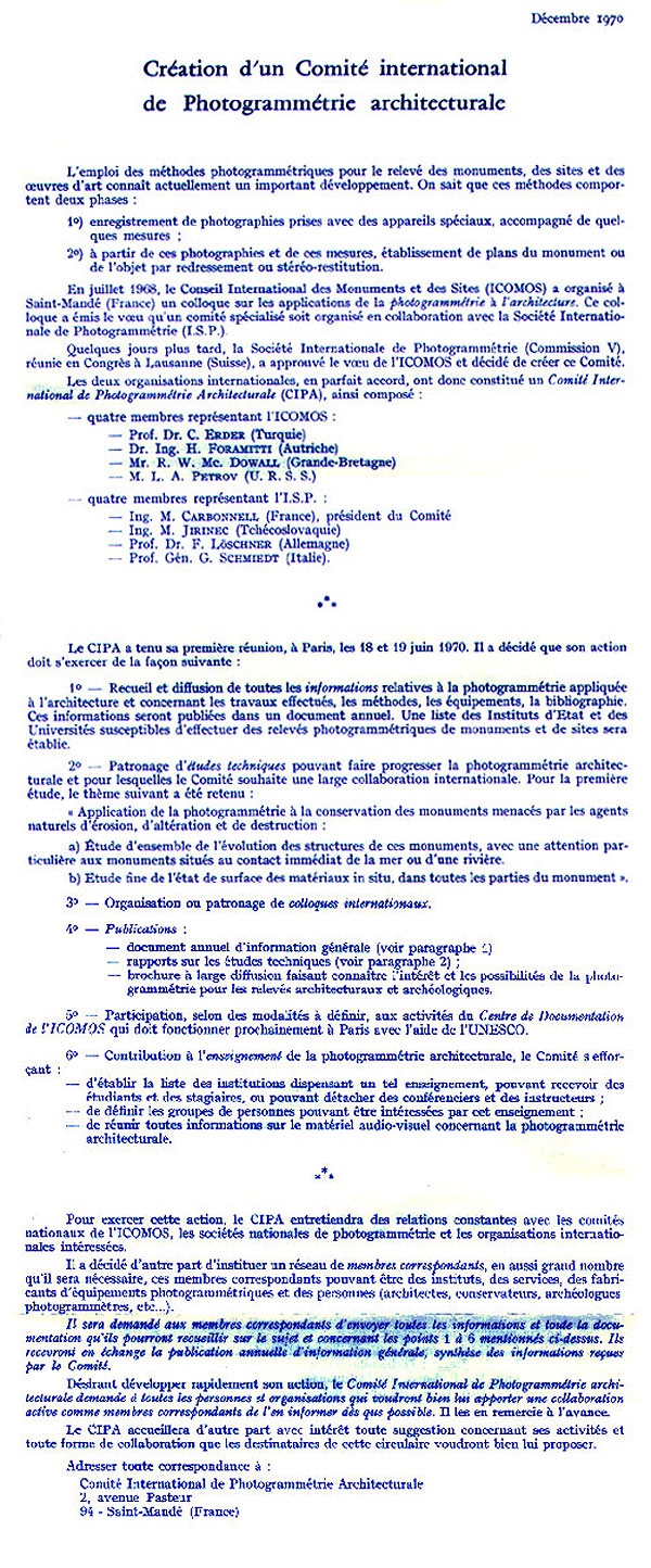
Constitution of the C.I.P.A.
the cultural heritage card
the open archive
the restitutor online
stereoscopic vision
the shooting base
the return
photogrammetry DIRECT
the stereo design
photogrammetry REVERSE
the stereometric model
the measure of distance
the photopiano
the geometric bases
the metric chamber
the digital camera
the coordinates
export data
importing data
the metric frames
the mobile brand
the origin of the system
the precision of the survey
the aiming
data recording
the room test
the graphic rendering
the drawing
digitization
the calibration operations
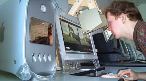
StereoFot® 7.2
instructions
PHOTOGRAMMETRIC ARCHIVE OF ARCHITECTURAL HERITAGE
Laboratory of Architectural Photogrammetry of the Polytechnic of Bari
Italian translation with Google
The Charter of Cultural Heritage of Puglia
The thirty-year activity of the architectural photogrammetry laboratory of the Polytechnic of Bari was based on three basic principles:
- " Know to protect ". The preservation and circulation of a historic car is possible only if there are deep connoisseurs of engines, otherwise even a "Ferrari" becomes an expensive, dangerous and polluting vehicle to be sent for demolition;
- " A good relief is already half the project ". A project worthy of the name comes from an in-depth analysis of what exists. The set of analyzes, carried out over time, allows an anamnesis of every cultural asset, which "is born, lives and dies" and, like every living being, is transformed and needs treatment, always based on an updated anamnesis;
- " The documentation of the Cultural Heritage is not for few and no one can delegate it. It is important that we teach it and give ourselves the tools, then it is the story that will speak about our culture ". A cultural asset is such if it is a source of culture, therefore it must be studied, starting from the relief, which obviously cannot be reduced to a simple graphic representation. If the "Architectural Photogrammetry" was included in the schools of any order and grade, the interested students could adopt a monument and update the form during the entire course of study, feeding, at no cost, the online archive.
Based on these principles, all the surveys taken care of by the laboratory, from 1976 to 2008, were put online, giving life to the "Charter of Cultural Heritage of Puglia":
Of great importance are the surveys carried out by the Photogrammetric Unit of the Bari Traffic Police in the areas affected by the 1980 earthquake.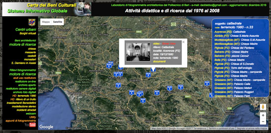
Selecting, for example, the item "earthquake (1980)" , a menu opens with the list of all the monuments detected, and, selecting one of them, a sliding panel opens , containing the list that shows, on each line:- the pair of frames;
- the button to call the panel of the restitutor;
- the subject of the shoot;
- the name of the monument and the detail taken;
- the numbers of the shot and the card;
- the location and date of shooting;
- the operators, the format of the frames, the camera and its serial number, the shooting base and the main distances of the objectives;
- the inclination and decentralization of the chamber.
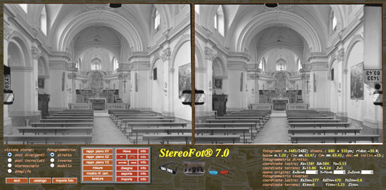
With unclick on "Restitution" the restitutor panel opens, with the couple of the selected frames, which allows the stereoscopic vision and the use of the same.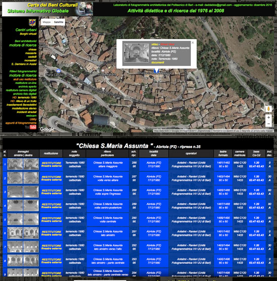
At the bottom of the panel are all the images existing in the archive and relating to the chosen monumento.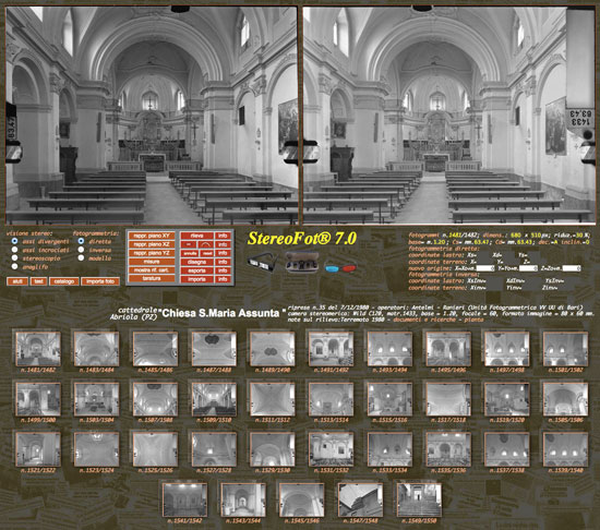
The open archive
Forty years later, the open photogrammetric archive of Architectural Heritage seems to have achieved the objective set by the C.I.P.A. (Comité International de Photogrammétrie Architecturale) in its first meeting (Paris, 18 and 19 June 1970), that is the establishment of an international archive of Photogrammetric Surveys of Architectural Heritage, duplicated and appropriately located in two safe centers .
The main difficulties that hindered the creation of this archive were essentially:
- lduplicate frames . At the time, terrestrial photogrammetry was derived from aerial photogrammetry, aimed at graphic restitution, giving primary importance to precision. Therefore the metric chambers used, as a support for the sensitive emulsion, rectified glass plates, of low sensitivity and, consequently, of high contrast. The duplication, besides involving a not negligible cost, was not exempt from a degradation of the image;
- the different format of the metric chambers . Each house, manufacturer of photogrammetry tools, chose its own format and, consequently, each room required its own restitutor, which in addition to the particularly high costs, could only be used by specialized operators. The two central archives would have required prohibitive costs, both because of the non-depreciable equipment and because of the scarce use.
- the use of frames . When we talked about photogrammetric survey, we referred exclusively to the graphic restitution, which, made in specialized laboratories, ignored the needs of those who had to use the survey, so much so that these, also for economic reasons, preferred to resort to the metric tape. The stereometric pairs of frames, not only were not used for the very poor knowledge and diffusion of stereoscopes, but were doubled as they were considered "copies"
Once the concept of " normal case " has been clarified, anyone can calibrate their camera and use three simple equations of 1st degree to schedule the return.
The StereoFot® 7.2 program, with its own archive, wants to be a concrete example.
If you think that:
- the current digital cameras automatically provide a series of information, including the main distance and geographic coordinates;
- the internal orientation of the frame is fixed, in fact the film no longer exists, subject to deformation, displacement, etc .;
- duplicating frames is a "no problem"
- the framing and the precision of the shot, with a minimum of organization, can be verified on site, with the advantage, thanks to a simple key, of being able to store the frames in real time (in fact it has failed the process of developing and printing the frames with the relative long technical times);
it can be safely said that the only problem to solve, in order to carry out the survey, is to take the two photos without changing the direction of the optical axis: in practice it is sufficient to slide the camera along an "L" bar and measure the moving anywhere in the room.
For the return it is sufficient:- click on the "import photo" button;
- insert the requested data (the indispensable ones are marked in red);
- click on the "register" button
- carry out the calibration, if the frames are loaded for the first time;
As for the results and, in particular, the accuracy of the survey, all that remains is to rely on the law of the Internet: unnecessary findings will not be consulted and will go down in the ranking!
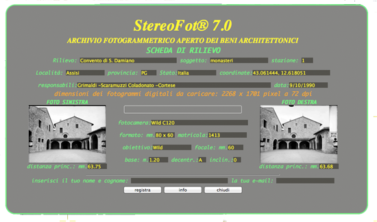
The renderer online photogrammetric
The photogrametry allows, through a couple of photographs, taken with a particular technique, to know the spatial coordinates of each point observable on both frames. There is talk, more precisely, of stereophotogrammetry, and should make the distinction between:
The digital photogrammetry allows you to do this via the network.
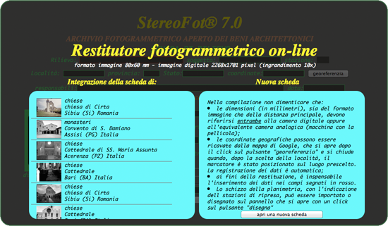
In the opening window, under the heading " Integration of the tab of: ". a scrolling field appears, containing the reliefs already started.
If the desired survey exists, with a click on the field line, the already filled in form is recalled (except for the field concerning the "station"), but which can be changed manually (for example if a room with different features). In addition to the station number, the position of the same on the plan should be added to the plan, which must be called up with a click on the corresponding button;
it is taken for granted that the shot must have been made in full respect of the "normal case" and (another condition to be respected) the original format of the frames is 8x6 cm., digitally enlarged ten times, that is 80 x 60 cm. (2268 x 1701 pixels with a resolution of 72 dpi).
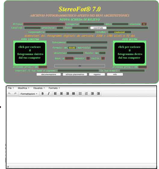
On the tab there are two large buttons, which must open the dialog for selecting images, then, in order, the fields for writing:
Stereoscopic vision
To detect the coordinates of a photographed point, it is necessary to detect the coordinates of its image on the left and right frames. For this purpose, on the frames it is possible to move (using the keys) a "brand" whose coordinates are known in the reference system of the respective frames.
Obviously, in the case of discontinuous surfaces (which have vertices and edges), it is possible to position the two marks separately on the corresponding points, but in the case of continuous surfaces, such as spheres or cylinders, stereoscopic observation of the frames themselves is indispensable.
In this restitutor the frames are prepared for viewing with:
When the program opens, the "diverging axes" button is already selected and it is possible, with the help of specific keys, to position the "movable marks" on the points correspondents.
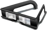 For stereo viewing, the right frame must be observed with the right eye and the left frame with the left eye. Considering that the distance between the corresponding points is greater than 6-7 cm., For this observation it becomes essential to diverge the visual axes.
 If you do not want to make use of special glasses , the obstacle to overcome is not very different from what those who approach the piano have to face: in this case it is necessary to do exercises to make the hands independent, in our case it is necessary to do ocular gymnastics, to make the eyes independent in movement.
This type of observation takes advantage of the ability, which everyone has acquired since childhood, to "converge the eyes" and this allows you to observe with the right eye the right frame, placed on the left, and with the left eye the frame left, located on the right.
Initially you will see the two frames oscillate, but with a little training you can make them overlap and observe a single image in relief.
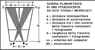
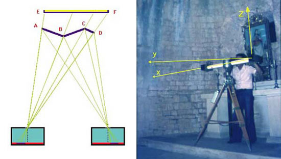
By continuing the training, you can also follow the mobile brand and make the return. In case of difficulty we recommend the use of a viewer, made according to the planimetric diagram below, where:
 |
|
In practice, the viewer exploits our ability to cross the visual axes: to look at the monitor, through the only opening placed in the center of the screen FF , the observer is forced to cross the visual axes, directing them on the two frames, whose position has been inverted just to make sure that the right eye only sees the right frame and the left eye only the left frame. The central septum G is intended for beginners, led to observe both frames with both eyes.
The stereoscope is an instrument that, through a pair of eyepieces, allows a comfortable vision of the stereo image, directing, thanks to a system of mirrors, the visual axes of the right and left on the respective frames. For comfortable viewing, simply adapt the stereoscope eyepieces to your interpupillary distance.
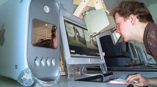
The Wild ST4 stereoscope adapted to the 22 "screen of the Mac G4.
We speak of anaglyph when, for observing the right image with the right eye and the left image with the left eye at the same time, use of complementary color filters. In our case, red is provided for the left eye and cyan (green-blue) for the right eye.
To check whether the colors of the glasses are complementary to those shown on the images, it is sufficient to bear in mind that with the red filter only the image turned red should be visible and with the other filter (cyan) only the other image having the same color.
The mobile brand, in stereo vision, takes on a single yellow color and the movement using the keys is a function of the network speed and the computer available.
The programming was carried out in HTML 5 and the coloring of the images in red and cyan (blue-green) if, on the one hand, thanks to the anaglyphic glasses, allows a valid stereoscopic vision, on the other it involves a "weighting" which requires a good network speed and a good computer, as well as a minimum of training in case you need to carry out the points.
In any case, to improve the observation, you can overlap the area you are interested in, with the help of the bar with the cursor below, while to carry out the survey of a point, proceed as follows:
- click on the image of the point. Without the glasses you will see two images. In this case, click on the right image (in red). With the glasses you will see a single image in relief and two cursors. In this second case, move the red colored cursor (on the left) to the chosen point;
- after the click, the image is enlarged and the mobile brand appears;
- use the cursor to position the mobile brand on the chosen point. Without the glasses you will see two images: one in red (on the right) with the brand positioned on the point and the other moved. With the aid of the cursor this must be moved until it overlaps the first one (for small movements use the Z and X keys).
- any adjustments of the mobile brand can be made with the help of the arrow keys and for the survey the procedure adopted for the "direct" is followed.
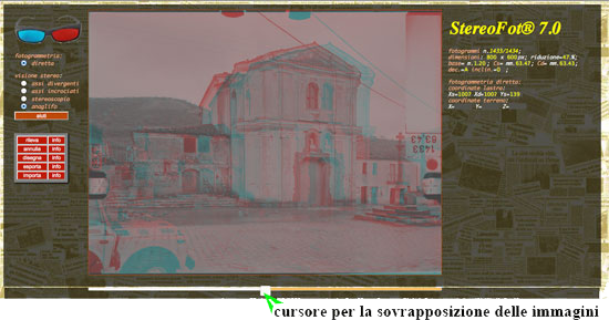
the image as APPRE after selecting the "anaglyph button"
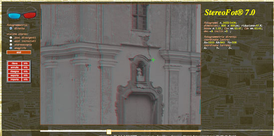
the mobile brand positioned on the chosen point

anaglyphic glasses
Terorically, any computer connected to the Internet allows the use of StereoFot. In practice, it should be borne in mind that the program must manage two images with 256 gray levels, with dimensions that vary from a minimum of 800 x 600 pixels to a maximum of 2268 x 1701 pixels, with a resolution of 72 dpi. The software was developed and then tested on a Mac computer with a 1.3 GHz processor, with 4GB 1600 MHz DDR3 memory.
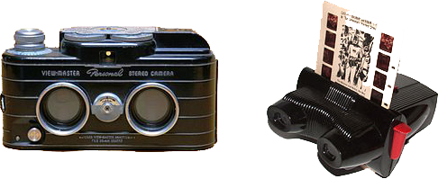
stereocamera and stereoscopic viewer
Looking at the two photos with the stereoscope, the child sees a single three-dimensional image in the center, which he indicates with his finger.
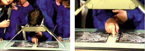
Wild ST4 stereoscopic
Observing, for example, a pair of frames taken with a base of 3 meters, one would have the vision of a hypothetical giant, whose eyes are three meters apart. Considering that each of us, to better observe an object, takes it in his hands and in this case the relationship between the interpupillary distance and that of the object is on average 1/10, in photogrammetry the relationship between the base and the distance of shooting varies between 1/5 and 1/20, so you can observe the virtual model of the object taken, reduced in scale, at an average distance of one meter. The following diagram shows the model taken with base b1 and the virtual model observed with base b2 , reduced in the same scale as the base. It should be noted that, in the scaling of the model 1-2-3 only the distance between the frames varies, the dimensions of which remain unchanged.
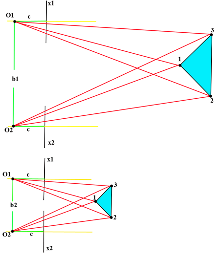
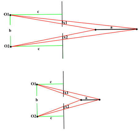
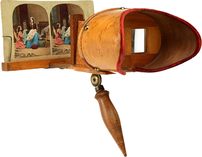
Direct photogrammetry
Direct photogrammetry allows you to observe the three-dimensional model of the photographed object, reduced in scale to be observed at a distance of about one meter and allows the relief of the visible points on the pair of frames with:
- calculation of the coordinates x, y, z in a Cartesian reference orthogonal with the origin in the left chamber;
- numbering, in the order of execution, and filing in appropriate fields;
- export of these points to the server;
- import of the same, for the purpose of possible integration of the survey.
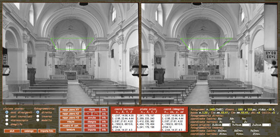
Taking for granted that the pair of frames has already been chosen from the General Catalog and, therefore, we already have the relevant screen, to carry out the survey it is necessary to:

- select the radio button direct ;
- when the cursor is on the frame taken from the left, it takes the form of a cross, then click on the chosen point. The image is enlarged and it is possible to position the mobile brand with precision, using the " arrow keys ". Obviously if these are easily identifiable points, it is possible to position the mobile brand first in the left frame and then in the right frame, otherwise stereoscopic vision becomes indispensable;
- with the help of the " C " and " V " keys, center, with the mobile brand, the corresponding point on the right frame (in the view stereo of the frames, the mobile brand moves deeply);
- with the click on the " finds " button, or by pressing the button " A " the data (coordinates-terrain and coordinates-plate) are temporarily stored in the corresponding fields. The third "horizontal plane" field stores the coordinates of the points detected, projected on the horizontal plane. Obviously, when the recovery is made with horizontal axes, these coordinates are the same as those stored in the first field.
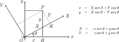
- repeat the operation for the other points, bearing in mind that in the representation they will be connected in sequence;
- to interrupt the line , which will connect the points, the button with the dash must be used (below the "detect" button);
- if you are in the presence of a round arch, taken from the front, you can use the button marked by a semicircle, which sets the arch, and then detects the two tax points;
- click on the " draw " button to represent the survey carried out;
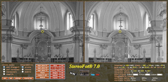
- with a click on the " export " button a dialog box opens that allows you to assign a name to the survey, with a click on OK the data is stored on the server;
- with the import button a panel opens with the list of findings on the server, among which we can choose the one to be recalled for appropriate additions. After clicking on the button, the data is shown in the three fields reserved for the coordinates.


The stereo design
The "draw" button draws, on both frames, a line that joins, in sequence, the points detected and recorded in the scrolling field.
Obviously the graph, observed under the stereoscope, appears three-dimensional.
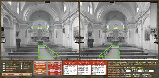
reliefs of details in the cathedral of Abriola (PZ)
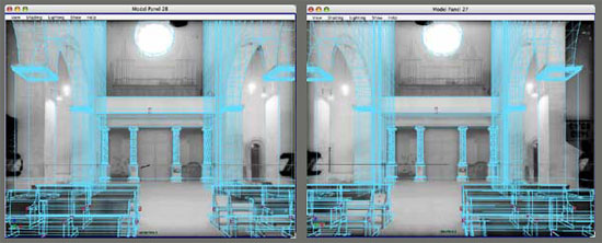
restitution of a couple of frames of the Cathedral of Acerenza
The bi-univocal correspondence between the plate-coordinates and the soil-coordinates, allows to obtain the former as a function of the latter. This becomes particularly useful in the design, because it allows you to draw directly on the image of the area subject to the design transformation.
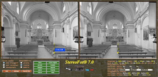
- have a stereoscope or, in any case, glasses for stereoscopic vision, indispensable for controlling the movements of the mobile brand, which can only take place with keyboard commands;
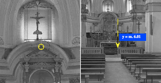
- select the radio button "inverse" . The mobile brand is replaced by a yellow-black colored pole, which in the photo on the left is flanked by a field, colored in blue. When the pole is moved in one of the three directions x, y, z the field shows the value of the relative coordinate.
The pole can be positioned on the chosen point:
- with the arrow keys, for movements in the XB plane (the unitary movement of the pole is 1 cm, while with the "ctrl" key lowered it is 10 cm);
- with " C " and " V & quot, for displacements in the direction of the Y axis (depth). - select the "detect" button to temporarily store the coordinates of the pole in the fields "terrain coordinates" and "frame coordinates" . The points detected will be connected by a line in the same sequence as the survey.
- the operation must be repeated for all the points concerned.

- the origin in the lens of the left camera;
- the X axis in the direction of the joint between the objectives of the chambers, directed towards the right camera.
- the Y axis in the direction of the optical axis of the left camera, directed towards the imaged object;
- the Z axis directed upwards, orthogonally to the XY plane.

- with a click on the button "new origin" it is possible to move the origin of the reference system to the point where the pole is located.
- with the button "draw" , the points detected are connected so as to represent a geometric figure that can be colored by selecting the button "color".
- with the "export" button the detected points are exported to a document on the server, to be recalled with the "import" button;
- to measure the distance between two points A and B use the "measure" button:
- move the pole to point A and click on the corresponding radio button;
- move the pole to point B and click on the corresponding radio button;
- read the distance, measured in meters, in the field below (AB = m. ....).
- with a click on the "model" button, the points detected (whose coordinates are contained in the first field) are connected, in the sequence of the survey made, and the graph obtained can be moved:
- in the XZ plane using the arrow keys;
- in the direction Y with the " C " and " V & quot.
- The data of the survey are shown at the bottom right of the panel

The stereometric model
This function can be particularly useful for checking the environmental impact of a volume and, with the indispensable use of stereoscopic vision, it takes the following steps:
- selection of the " inverse" radio button to switch to the inverse photogrammetry mode;
- detect points intended to identify the volume you intend to represent or import a model from the library. The relief of the volume, which is intended to be represented, is given by the set of points contained in the "coordinates" field;
- selection of the draw button for the representation of the model numerically present in the field on the right ( coordinates-terrain );
- selection of the model button to store the model;
- selection of the radio button " model" to move the model in the xyz system, which has its origin at the left pick-up point. In particular:
- with the arrow keys the model is moved in the xz plane;
- with the " C " and " V & quot" keys, the movement takes place in the y direction (depth).
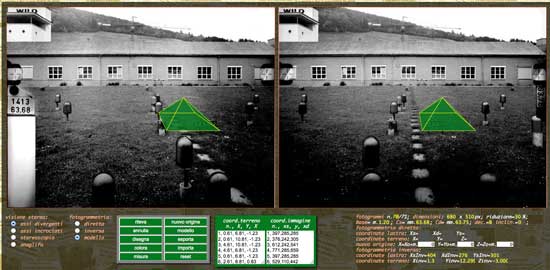
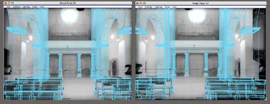
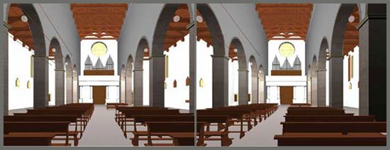
Two examples for an idea of the virtual stereometric model:
- the virtual arrangement of a pyramidal solid in the test field
- the stereometric modeling of the interior of the Cathedral of Acerenza (PZ)
Measurement of the distance between two points A, B
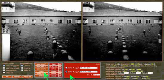

- Fotogrammetria diretta:
To measure the distance between two points A and B in the case of direct photogrammetry ("direct" radio button; selected):
- click on the " measures " button;
- place the mobile brand on point " A ";
- click on the " detect " button;
- select the radio button of point A (the coordinates will appear in the relative field);
- repeat the operations for point " B "
- read the distance measurement " AB " (provided in meters) in the relative field located at the bottom, on the right of the panel.
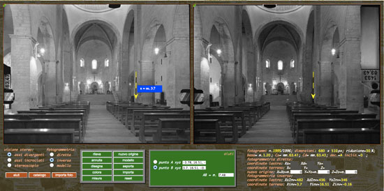

- Reverse photogrammetry :
In the case of reverse photogrammetry ("inverse" radio button; selected), the mobile brand is replaced by a yellow-black pole (accompanied, in the left frame, by a blue field with the values of the varied coordinate) which is controlled exclusively from keyboard (arrow keys for movement in the xz plane, the C and V keys for movement according to y (depth):
- place the mobile brand on point " A ";
- select the radio button of point A (the coordinates will appear in the relative field);
- repeat the operations for point " B ";
- read the distance measurement " AB " (supplied in meters) in the relative field (bottom right).
The photoplan
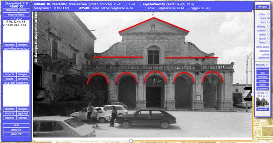
When you are in "direct" mode and select "representation in the XZ plane" , a panel opens for the representation of the points detected.
Pressing the "Import relief" button, located at the top left, opens the list of existing reliefs in the archive. By selecting one of these, the coordinates appear in the field below the button itself, while the left frame appears, in reduced format, at the bottom, in the right button panel.
With a click on the "show" button , placed under the photograph, this can be called up on the screen. In the absence of the relief, you can use the "import" button (existing on the push-button panel, bottom right), which opens a dialog box, shown below, to directly call up the photograph.
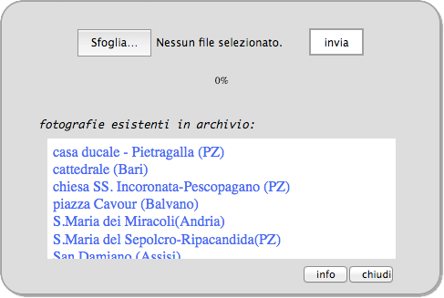
- the radio button " PHOTO ", selecting which it is possible, with the cursor that takes the shape of a hand, to move the frame on the plane;
- the imported " frame number ";
- the " frame " in reduced dimensions;
- the button " show " (or " hide "), with which the frame present in the icon is recalled.
- the " import " button, which allows you to use frames or photographs on your computer (size 2268 x 1701 pixels at 72 dpi).
The sliders on the scroll bars allow you to vary the frame size from 0 to 2268 pixels horizontally and from 0 to 1701 pixels vertically (original frame size).
The geometric bases
This restitutor has been programmed for the restitution of photogrammetric surveys performed according to the so-called "normal case", ie with the optical axes of the chambers arranged orthogonally to the base (joining the two chambers).
In the planimetric representation of fig. 1 two cameras are schematized and colored in yellow which capture point P, whose image is projected, through the lenses O1 and O2, on the frames (segments colored in blue).
If the cameras are arranged with the optical axes of the parallel lenses and with the coplanar frames, the two formulas shown in the figure can be obtained from the similarity of the triangles, outlined in the figure.
Taking into consideration the Cartesian system XY , we can detect a one-to-one correspondence between the coordinates ( x, y ) of the point P and the linear coordinates x ' and x " (in the frame reference system) of the images of the same point.


Meanwhile, we note (from the formulas) that any error in the measurement of the c (main distance) affects only the y (profodity), intervening heavily, because measured with the precision of the hundredth of a millimeter. To get an idea of the influence of the different parameters, let's assume that we have the data colored in green in the following table and we change the values colored in red by 1/100 (in the last row the main distance has been rounded ):
| base | c | x' | x" | x | y |
| 1,20 | 63,68 | 5,96 | 3,08 | 2,48 | 26,53 |
| 1,21 | 63,68 | 5,96 | 3,08 | 2,50 | 26,75 |
| 1,20 | 63,69 | 5,96 | 3,08 | 2,48 | 26,53 |
| 1,20 | 63,68 | 5,97 | 3,08 | 2,47 | 26,44 |
| 1,20 | 63,68 | 5,96 | 3,07 | 2,49 | 26,62 |
| 1,20 | 63,00 | 5,96 | 3,08 | 2,48 | 26,25 |
The metric chamber
The metric camera is a camera, equipped with a high quality lens, whose external orientation and internal orientation are known, meaning by:
- external orientation , the orientation of the camera at the time of shooting. In practice, in the normal case , it limits us to detect the inclination of the camera on the horizontal plane, as well as the orthogonality with respect to the base (as the joining of the two points of recovery is defined);
- internal orientation , the orientation of the beam of rays, projecting the image on the sensitive surface, with respect to the surface itself. In practice, this orientation is detected at the factory ( chamber calibration ) and is provided with the main distance and the main point meaning by:
- main distance , the distance between the center of projection and the sensitive surface at the time of shooting. Considering that the metric cameras are fixed focus, this distance is a characteristic of the camera and is imprinted on the frame;
- main point , the point of intersection of the joining opposing marks, imprinted on the four sides of the frame.
The shooting chamber, for which this program was written, is the Wild C120 stereocamera, supplied to the Laboratory of Architectural Photogrammetry of the Poitecnico of Bari and to the Photogrammetric Unit of the Bari city police.
These are two metric chambers, rigidly connected at a distance of m. 1.20 (base) and synchronized in the shot, whose main features are:- focal 60 mm . By focal is meant the distance between the center of projection and the plate, when the "focus" is on infinity, while by main distance is meant the distance mentioned above, measured with an accuracy of 1/100 mm. at the time of shooting (fixed distance and measured at the factory in the case of fixed focus cameras). This explains why the stereocamera has two cameras with the same focal length, but different main distances;
- base 120 cm. The basic objective of photogrammetry is to put the model within arm's reach three-dimensional object photographed. Considering, therefore, that the distance between the eyes ( observation base ) is 6 cm. and the distance of an observed object, held in the hands, varies on average between 25 cm. and one meter, the base / distance ratio varies between 1/5 and 1/25. Therefore, in order to have this ratio in the photogrammetric acquisition, the acquisition base must be between 1/5 and 1/25 of the distance to which the object to be detected is found. In our case, with the base of 1.20, we can detect objects placed at a distance of between 6 and 24 meters .;
- 6 x 9 cm plate format. The Wild C120 stereocamera accepts 6x9 cm oven plate holder chassis and is equipped with two 12-chassis magazines each;
- image format 60 x 80 mm. The supporting framework of the slab, in the Wild C120, measures 6x8 cm. and on the vertical edges, at 2/3 of the height, it bears two brands, half illuminated by sunlight and the other half by battery lamp. The distance between the brands measures 75 mm. and at the center point there is the main point , intersection, with the plane of the plate, of the perpendicular from the center of projection of the image to the plate itself. The Cartesian reference xy , established on the frame, has:
- the origin at the main point; - the x axis along the line joining the brands themselves and with a positive sense to the right; - the axis y in an orthogonal direction and with a positive sense upwards; - vertical decentralization 10 mm. The Wild C120 camera was created to detect road accidents, therefore it was designed to have a greater angle of recovery downwards in a horizontal position. For this reason the main point is not in the center of the frame, but is moved upwards by 10 mm. Subsequently, the chamber was equipped with a head that allows it to be turned upside down (so as to have decentralization downwards and a greater angle of recovery upwards).
- tilt . With the adoption of the head, the stereocamera can make inclined shots of 10 °, 30 ° 60 ° and 90 ° for zenith shots;
- horizontal shooting angle . the horizontal viewing angle of the stereometric chamber is that common to the two chambers and is 60 °. It should be borne in mind that the shooting angle of a camera is the angle at the top of a triangle which has as its basis one side of the frame, by height the focal length (or, to be precise, the main distance) and the vertex on the perpendicular conducted for the main point.
- vertical shooting angle. Thanks to the decentralization, this is asymmetrical and measures 17 ° upwards and 33 ° downwards or vice versa, in the event of overturning.
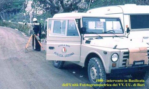
the Wild C120 stereocamera supplied to the Photogrommetric Unit of the Urban Police of Bari
Digital camera
When you do not have a metric camera and you want to proceed with a common camera, you must take note of the main drawbacks that you face and which can be summarized as follows:
- quality of the objective, which should be free from distortions;
- main distance, which in metric chambers is supplied by the factory;
- determination of internal and external orientation.
The digital camera, if referred to the analog camera and the resolution problem is considered overcome, has some advantages, such as:
- the image is no longer subject to the deformations that the film underwent, especially in the development phase;
- the planeity problem of the sensitive support no longer exists;
- there is no longer the problem of frame orientation in the restitutor. In fact, the fixed marks were a first consequence of the variable position of the plate or flat film inside the chassis. In the digital camera, used without automation, the position of the frame can be considered fixed;
- at the moment of shooting, the frame stores a series of information which, like those marked in red in the following list (Panasonic Megapixel Digital Camera), can be useful in archiving:
- Color space: sRGB
- Components configuration: 1, 2, 3, 0
- Bits compressed per pixel: 4
- Contrast: Normal
- Processed ad hoc: Normal process
- Digitized Date / Time: Feb 26, 2014 19:42:37
- Original date / time: Feb 26, 2014 19:42:37
- Digital zoom ratio: 0
- Exif version: 2.2.1
- Exposure tilt value: 0
- Exposure mode: Automatic exposure
- Exposure program: Normal program
- Exposure time: 1/13
- File source: DSC
- Flash: The flash did not fire, flash mode required
- FlashPix version: 1.0
- F number: 2.8
- Focal length: 4.8
- Film focal length 35mm: 27
- Gain control: Gain upwards
- ISO speed: 400
- Light source: unknown
- Maximum aperture value: 3
- Measurement method: Model
- X pixel size: 3.648
- Pixel size Y: 2.736
- Saturation: Normal
- Scene acquisition type: Standard
- Type of scene: Image photographed directly
- Detection method: Color area sensor (One-chip)
- Sharpness: Normal
- White balance: Automatic white balance
- AFInfo: 0.4750548, 0.4751462, 0.04989035, 0.0497076, f
- Image stabilization: 1
- Serial number: S030809300526
Before attempting the survey, it is advisable to be aware of at least systematic errors, limiting yourself to:- goal . The least that can be done is to photograph a squared surface, orthogonal to the optical axis of the lens, then to superimpose on the frame (with any photo editing program) a lattice and realize the existing deformations.
- external orientation . Having to take a shot according to the normal case , it is sufficient to move the camera (the movement corresponds to the base), respecting the orthogonality of the optical axis with respect to the two points of recovery (you can think of an L-profile, on which to place the chamber or to a sliding trolley).
- internal orientation . Considering that the orthogonal Cartesian reference system, determined in the recovery, has:
- the origin in the chamber, when it is positioned on the left;
- the X axis according to the direction of the line joining the resume points, with a positive sense to the right;
- the Y axis according to the optical axis of the camera, with a positive sense towards the photographed object;
- the Z axis, orthogonal to the XY plane and positive direction upwards;

you can choose a point, of which you can know the coordinates in the reference cited above, and, with the inverse formulas, obtain the main distance and the position, in the plane of the frame, of the origin of the orthogonal Cartesian reference, which is determined on the frame.In the StereoFot program, when you open a new tab, by clicking on the calibration button, a panel appears that allows you to obtain the data for the internal orientation, according to the criteria illustrated above. At the top are the fields to be filled with:- the size of the frames in pixels. To facilitate the positioning of the mobile brand , the frames (which are loaded with a size that can be contained on the computer screen used) can be enlarged beyond their size and, since the 4 x 3 format is provided, it is just type in the desired frame width;
- the shooting base, measured in meters, corresponding to the distance between the positions of any point of the camera in the two shooting stations;
- the x, y, z coordinates (in the reference above) of a point. for the calibration of the camera, it is advisable to materialize the reference system, considering that the data obtained will influence the precision of the measurements;
- a button that, pressed after positioning the mobile brand on the point chosen as reference, allows the calculation of the main distance and the decentralization (δx and δy) of the main point (origin of the Cartesian reference of the frame);
In the lower part, under the frames, there are:
- the plate-coordinates of the mobile brand;
- four radio buttons for checking distances AB and CD between points with parallel and orthogonal alignment to the base;
To realize the achievable precision:
- place the mobile brand on a point;
- detect the co-ordinated terrain with the "verification button P", located at the bottom of the panel;
- select one of the four radio buttons relating respectively to " base ", " main distance " and " decentralization Δx e Δy the main point ";
- use the X and Z keys to change the relative values, shown in cyan color;
- view the corresponding results, shown in the yellow (value) and red (difference with the cyan value) fields.
- click on them to transfer the individual values obtained in the upper fields, relating to the calibration.
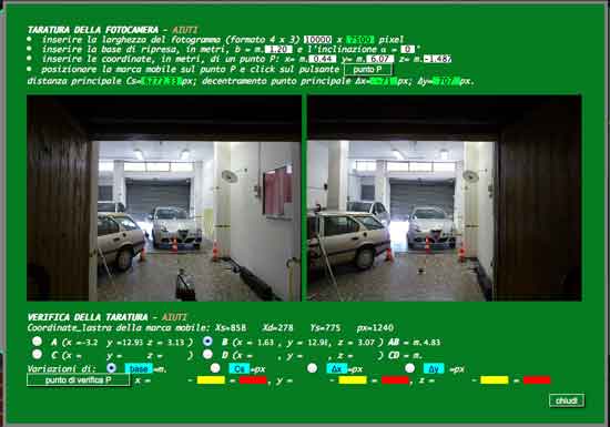
The calibration operations
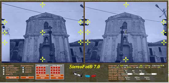
Four reference marks are imprinted on each metric frame, joining which the Cartesian reference of the frame is displayed, indispensable for detecting the coordinates of the points subject to the return.
In the case of the Wild C120 stereometric chamber, equipped with decentralized optics, the reference marks, present on each plate, are only two, placed at 1/3 or 2/3 of the height, according to whether the decentralization is, respectively, towards the 'up or down (the main point, of course, is located in the middle).
On the cards the decentralization indicated is the opposite of the real one, so that the decentralization " A " corresponds to a higher upward angle and vice versa.
The calibration operations consist in making the frame reference system coincide with that provided by the program.
To this end, by clicking on the " calibration " button, fixed reference marks appear on the frames and a panel with buttons is highlighted ![]()
![]()
![]()
![]()
![]()
![]() ,which allow you to rotate, as well as move horizontally and vertically, each frame, so as to make the brands impressed on the frame coincide with those of the picture.
,which allow you to rotate, as well as move horizontally and vertically, each frame, so as to make the brands impressed on the frame coincide with those of the picture.
The data is recorded in special fields, located to the right of the buttons and, in the if the frames are imported, they are stored together with the frames themselves.
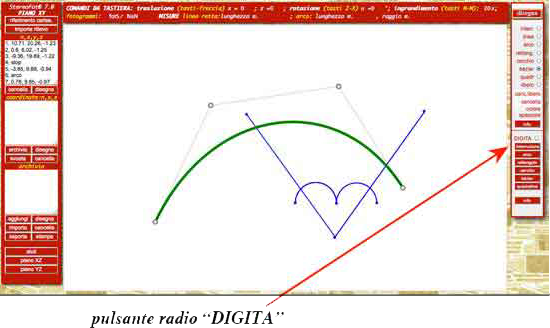
The following functions can be used for the analysis of the survey and the integration of the graphs by selecting the relative radio buttons:
- " break ". Stop any graphic function;
- " line " . Draw a segment joining the two points, in which the mouse is lowered and raised. The distance between these two points is shown on the upper bar (measurements - length);
- " arc " . Draw a round arc joining the two points, where the mouse is lowered and raised. The length of the arc and its radius are shown in the upper bar (arc - length - radius);
- " rectangle ". Draw a rectangle with the opposite vertices in the two points, where the mouse is lowered and raised;
- " circle ". Draw a circle with the center at the point where the mouse is lowered and the radius equal to the distance between the two points, where the mouse is lowered and raised;
- " bézier ". It has four handles, which allow you to give the curve the desired shape;
- " quadratic ". It has three handles, with which it is possible to give the curve the desired shape;
- " free ". Allows free hand drawing (mouse);
- " canc.libero ". Allows free hand drawing (mouse);
- " delete ". Clear the chart;
- " color ". Opens a menu for choosing the color;
- " thickness ". Opens a menu for choosing the line thickness;
Digitization
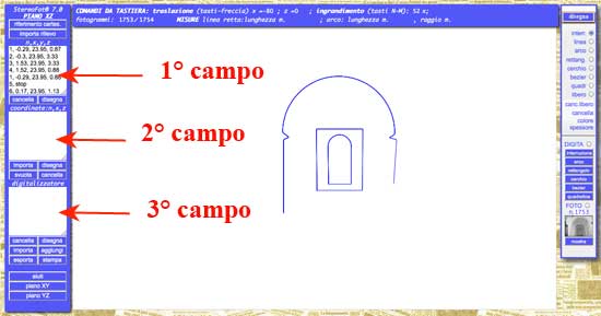
With the radio button " DIGITA " selected and the use of the buttons below, the coordinates of each point, where you click, are stored in the second field. This makes it possible to digitize any chart, bearing in mind that to digitize:
- " arc " , you need to click on the first tax point, press the "arc" button, then click on the second tax point;
- " rectangle " you need to press the "rectangle" button and click on two opposite vertices;
- " circle " you need to press the "circle" button and click on the center and on a point of the circumference;
- " bézier " you need:
- select the "bézier" button in order to make the curve appear, with the relative handles;
- click on the "bézier" button (white writing on a red background);
- click clockwise on the handles;
- " quadratic " you need:
- select the "quadratic" button in order to make the curve appear, with the relative handles;
- click on the "quadratic" button (white writing on a red background);
- click clockwise on the handles;
The graphic return
If you intend to make a graphic restitution, it is necessary to bear in mind that the photogrammetric survey provides the spatial coordinates (xyz) of all the visible points on both frames.
To represent, for example, the plan of a church, it is necessary not only to make several shots, but it will be necessary to integrate the information necessary to represent the points not visible in the photograph.
To check, therefore, the survey or, simply to take notes, three graphic tablets are available that can graphically connect the points detected, respectively in the planes xy (plan), xz (elevation) and yz (section), more precisely:
The precision test
To get an idea of the achievable precision it is advisable to use the frames of the Heerbrugg test field, supplied with the Wild C120 stereometric chamber, on which there are four reference targets arranged in a "T" and having coordinates in meters:
- x = 0,60, y = 6,00 (A, la più vicina);
- x = -9,40, y = 20,00 (B, a sinistra);
- x = 0,60, y = 20,00 (C, centrale);
- x = 10,60, y = 20,00 (D, a destra).

Data logging
Once the aiming has been carried out, ie after positioning the mobile brand on a point (practically on both frames), it is possible to register the coordinates with the "detect" button. By clicking on the latter, three scrolling fields appear, where the order number of the point itself, the ground coordinates xyz ( x according to the joining chambers, y according to the optical axis of the left chamber and z orthogonal to both), the plate-coordinates xy (origin at the main point, x axis according to the line joining the fixed marks and orthogonal y axis) and the ground coordinates on the horizontal xy plane.

- in the first field the ground coordinates are recorded in the reference xyz of the stereocamera;
- in the second the plate-coordinates x1, y, x2 (the ordinate y of the points photographed is identical on both frames);
- in the third field the ground coordinates of the detected points are recorded, projected on the horizontal plane, in a reference that sees the axes y and z rotated in so as to be respectively horizontal and vertical. Naturally the data of the latter field coincide with those of the first, when the recovery is made with horizontal optical axes.


The return
By restitution we mean the operation with which we obtain the ground coordinates of a photographed point, but the problem of finalization is to be addressed, since the person making the restitution is not the final user of the survey and, therefore, hardly knows what the details are to represent.
The possibility of having the three-dimensional optical model available made the old continuous return unnecessary. In fact, when the restitution took place in the laboratory, using very expensive equipment, observing the three-dimensional optical model, a representation of the photographed object was processed, in orthogonal projection in the xy (plan) or xz (prospect) plane, elaborates that were supplied to the user as the final product. Today, thanks to the digital restitutors, the user himself can detect information from the frames, or report new information on the same frames and we speak, therefore, of:
With the passage of photography from analog to digital media, moreover, thanks to the use of modeling programs, today more than reverse photogrammetry we are talking about stereometric modeling.
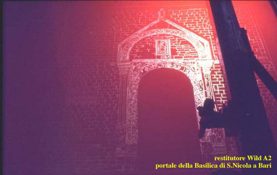
processing carried out with the Wild A2 universal restitution of a shot made with the Wild P30 phototeodoloite (1974)
The pointing
Any point, shown on both frames, can be reached in two ways:
- in direct mode (the simplest way), bringing with the ARROW KEYS the left mark on the interested point of the left frame and then using the " C "and" V & quot, only the right mark is moved to the corresponding point of the right frame.
This path, however, is passable when it is necessary to carry out surveys on continuous surfaces, without points significant: in this case it is essential to use stereo vision, operating in a similar way to that followed in reverse photogrammetry.
- in reverse mode, in stereovision, moving the mobile brand in the xz plane with the ARROW KEYS and along the y axis with the " C " and "< B> V & quot.
Initially, if you are not very experienced, when observing the three-dimensional image under the stereoscope, to make sure that the point is resting on the surface, it is recommended to make small movements along the y axis (forward and back): when the mobile brand goes beyond the detected surface, it should double.
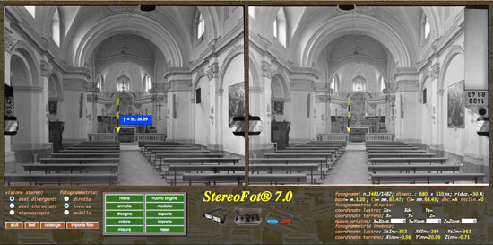
The precision of the survey
The degree of precision achievable is, as always, the result of a compromise.
To be taken in first consideration, there is the pointing error: even with the aid of stereo vision, everyone places the mobile brand on the point to be detected in a completely personal way.
Taking for granted that, during the recovery phase, the operator has never forgotten, before shooting, to fix the plate on the support panel, to this type of error we must add a series that we could define systematic and that, in the particular case , we could summarize as follows:
- the film must have been placed in the scanner in order to ensure its flatness. Otherwise the imprinted picture will not be rectangular; (on the edges of the frame you will notice triangular black areas);
- the scan in the two orthogonal directions can differ. In our particular case, the image format of the frames is 80x60 mm. with a base / height ratio of 1.33, but after scanning the image obtained has a 3448x2567 pixel format, with a b / a ratio of 1,34320218153487. In practice, after the scan, the height of each frame should have been increased from 2567 to 2586 pixels, but this was not done, because it is considered negligible;
- the plate has a displacement margin in the chassis, so its position on the support frame of the camera is not fixed, therefore almost always the image frame imprinted on the frame is rotated. In the scanning phase, then, everything is subject to another rotation. The correction of this rotation was done with Photoshop, using the reference marks.
- after the scan and the correction of the rotation, the frames were brought to the size of 800x600 mm. (2285x1701 pixels). With this magnification (10x) the distance between the reference marks should be 750 mm. and 25 mm. their distance from the edges;
- strictly speaking, in the enlargement of the frames, it would be necessary to take into account the distance between the reference marks (originally 75 mm.) Rather than the width of the frame, always cropped with little precision. In the restitutor, the main distance has undergone the same magnification of the frames (10x), but in reality it should refer to the enlargement of the distance between the brands. This operation was also neglected due to the very small existing gap.
Here, to get an idea of the achievable precision it is advisable to use the frames of the test field (the frames supplied with the stereometric chamber have been digitized), which, to operate in the most unfavorable conditions, were first reduced to size of 800x600 px and subsequently enlarged to the size of 800x600 mm. (2285x1701 px).
On these frames we can see four reference sights, arranged at " T ".
The first target has coordinates A (0.60, 6.00) and is set at 6 m., while the other B (-9.40, 20.00), C (-0.60, 20.00) and D (10.60, 20.00) are located at a distance of 20 m.
Focusing on the nearest one (6 m away. ) we easily realize that the measure varies between 5.99 and 6.02 m. (the error does not drop below the centimeter) and the explanation comes immediately from reading the fields, all with decimal values to be represented with non-divisible pixels!
Undoubtedly one could increase the size of the image and, consequently, the weight of the image (... to be transferred via the network), but is the expense worth the business ?
Origin of the xyz reference system
During the recovery phase, the origin of the xyz system of the ground coordinates is fixed at the recovery point on the left, therefore, even during the return phase, by default, the position of the origin remains unchanged and in the window, which appears after clicking on the "detect" button, we find, in the first field, the values (x, y, z), that is, the ground coordinates of the detected point.
In "reverse" mode, you can move the origin of the reference, where the mobile brand is located, using the " new origin " button. In this case, a dialog box asks for confirmation and, if so, the survey already carried out is deleted from the field, to make room for the survey with the new origin, the coordinates of which with respect to the original reference, are shown in the appropriate fields.
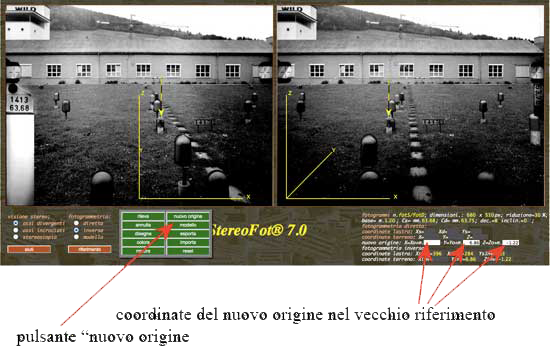
The mobile brand
The mobile brand, intended to be placed on the point to be detected, is represented by a small circle with four dashes, arranged in a cross and yellow, when using direct photogrammetry, and by a yellow-black pole, when reverse photogrammetry is chosen. As for the movements of the same, it should be borne in mind that:
- in "direct" mode, it is possible to move with the arrow keys both marks (right and left), in the frame reference system, simultaneously, while with the "< B> C "and" V & quot only the right brand moves in the horizontal direction (in stereo vision the brand moves deeply;
- in reverse mode, the mark moves to the xyz system, originating at the left pickup point. In particular, with the arrow keys the brand is moved in the xz plane, while with the " C " and " V & quot the movement occurs in the direction y (depth). A blue field shows the axis according to which the movement takes place, and the value of the relative coordinate.
The metric frames

- the base " b ", distance between the shooting points, measured in meters;
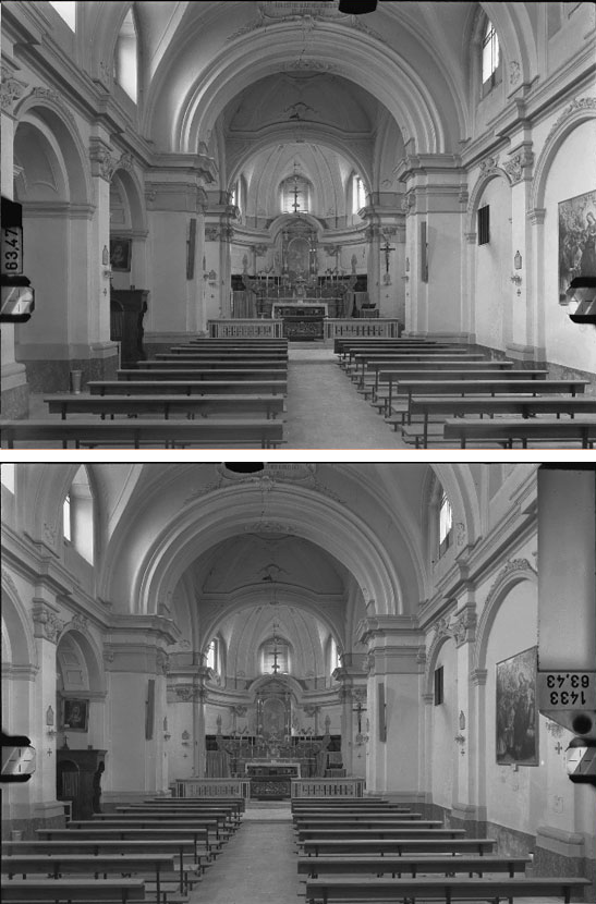
- the main distance " c ", the distance between the center of projection and the plane of the frame, measured in millimeters and shown on the frames (in this case 63.47 and 63.43), together with the serial number of the room (1433);
- the plate-coordinates " x1, z1 " and " x2 ", for which the origin of the Cartesian reference system is represented by the intersection of the optical axis with the plane of the frame ( main point ) and is identified by "brands" impressed on the frame (in this case the brands are two and the origin of the system is found at the center of the connecting line);
- the flatness . Originally, rectified glass was adopted as a support for the sensitive emulsion (hence the name "plate", still adopted today);
In the air chambers (with a format of 23 x 23 cm.), When, for obvious practical reasons, the "film" was replaced by the "slab", the back (perfectly flat) of the same was equipped with a series of suction holes, thanks to which, when the photograph was taken, the perfect adherence of the film and, therefore, its flatness was ensured.
In the case of the Wild C120 stereometric chamber, created for rectified plates (size 6 x 9 cm.), On the occasion of the intervention in the earthquake zones, flat films of the same format were used, which, before each shooting campaign , were "glued" on slides, made adhesive with a special spray.
For digital restitution, the negatives, of the 60 x 80 mm. Image format, obtained with a Wild C120 stereocamera, were digitized at 72 dpi, with dimensions 3645x2715 pixels (128x95 cm.) With an EPSON 1640SU scanner and reduced to the dimensions of 2269x1701 pixels (80x60 cm.), Ten times greater than the original format. - l ' deformability . Undoubtedly, with the passage from the plates to the films, things have not improved, but in our case, with shots taken at distances not exceeding 30 m., The consequences can be considered negligible.
With the transition to digital, then there was a further deterioration, due to the systematic deformation of the scanner and the not always accurate flat position of the film in the scanner itself;- dimensions . it is quite evident that the higher the frame format the lighter the reading of the same.
In aerial photogrammetry the format is 23x23 cm. while in our case the slab has a size of 6x9 cm. with an image format of 6x8 cm. With the transition to digital, a compromise had to be found between the format, which should have been as large as possible, and the weight, which on the contrary should have been as small as possible, to be broadcast via network. In our case, the format of 800x600 mm was chosen. (2285x1701 px), with a 10x magnification, for reading points, and a format of 800x600 px, for viewing under the stereoscope. A further reduction (indicated in the appropriate field) is made to adapt the window to common monitors. - dimensions . it is quite evident that the higher the frame format the lighter the reading of the same.

Importing data
With the "import" button it is possible to import, from the server archive, the ground coordinates and the plate coordinates (which will be arranged in the respective fields) of the previously detected points.
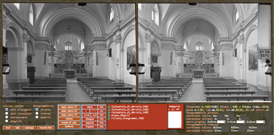
it is clear that whoever owns the data in his own archive, thanks to the copy-paste, can copy the data from his own document and insert them in the respective fields.

Data export
With the "export" button it is possible to export, in the server archive, the ground coordinates and the plate coordinates (contained in the respective fields) of the detected points, after assigning a name to the document in the dialog.
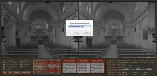
it is clear that whoever wants to keep the data in his own archive, thanks to the copy-paste, can copy the data on his own document.

Annulla
it is possible to undo the last survey performed with a click on the " undo " button, after confirming in the appropriate dialog.
To clear all three fields use the " reset " button.

When we talk about coordinates, in photogrammetry, we have to make a distinction between;
-
coordinates-sheet
- origin at the center point of the line joining the brands themselves;
- X axis, according to the joint itself, with a positive sense to the right;
- Y axis, according to the axis of said joint, with a positive upward direction.
On each frame, at the moment of shooting, two reference marks are imprinted on vertical edges, intended to determine an orgonal Cartesian reference with:
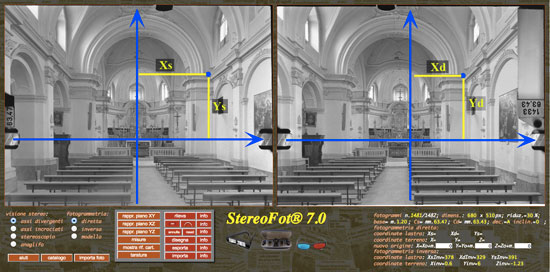
- the abscissa Xs of the left mark;
- the abscissa Xd of the right brand;
- the ordinate Ys of the left brand, which is the same for the right brand Yd .
By clicking on the "detect" button , these coordinates are recorded in a special field, to be exported to the server archive.

- The ground coordinates
The Cartesian coordinates of all points, present on the stereometric frames and identified by the mobile brand, are part of an orthogonal monometric Cartesian reference having:- the origin at the resume point on the left;
- the x-axis in the direction of the line joining the two pickup points with a positive direction to the right;
- the y axis coinciding with the optical axis of the left camera with a positive direction towards the object taken;
- the z axis, perpendicular to the xy plane with a positive sense upwards.
With a click on the button "show ref. Cart." it is possible to view said system on both frames.

Filmed with the Wild C120 stereocamera
- The ground coordinates